Individual Assignment
Group Assignment
Table of Contents
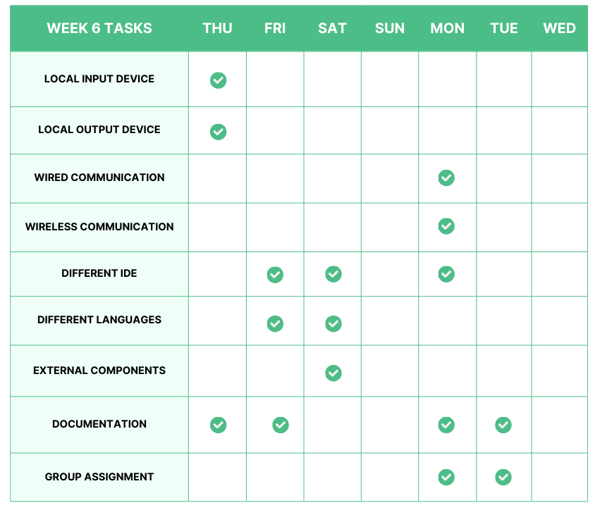
Week 6 Work Plan
This week starts by learning about embedded programming and how to program the XIAO-RP2040 development board, which was built in week 4. My instructor, recommended that we use Arduino IDE to program the XIAO microcontroller board.
Seeed Studio XIAO RP2040
The Seeed Studio XIAO RP2040 is a microcontroller board based on the Raspberry Pi RP2040 chip. The Raspberry Pi RP2040 is a microcontroller designed by the Raspberry Pi Foundation, and it features a dual-core ARM Cortex-M0+ processor.
- RP2040 Microcontroller: The board is powered by the Raspberry Pi RP2040 microcontroller, which features a dual-core ARM Cortex-M0+ processor running at a clock speed of up to 133 MHz. This microcontroller is specifically designed for embedded applications and provides ample computing power for various projects.
- Compact Form Factor: The XIAO RP2040 is likely to have a small and compact form factor, making it suitable for projects with limited space or those that require a lightweight and portable design.
- GPIO Pins: Like other microcontroller boards, the XIAO RP2040 is expected to come with a set of General-Purpose Input/Output (GPIO) pins. These pins allow users to interface with sensors, actuators, and other electronic components, enabling a wide range of applications.
- USB-C Connectivity: The board may feature USB-C connectivity, allowing for easy programming and data transfer. This feature simplifies the development process and facilitates communication with computers and other USB-enabled devices.
- Open-Source Design: Seeed Studio is known for its commitment to open-source hardware, and the XIAO RP2040 is likely to follow this trend. This means that the design files, schematics, and other documentation may be available for users, encouraging collaboration and modification.
- Community Support: Given Seeed Studio's reputation and the popularity of the Raspberry Pi ecosystem, the XIAO RP2040 is likely to have a supportive community. This can be beneficial for users seeking assistance, sharing projects, and exploring additional resources.
| Item | Value |
| CPU | Dual-core ARM Cortex M0+ processor up to 133MHz |
| Flash Memory | 2MB |
| SRAM | 264KB |
| Digital I/O Pins | 11 |
| Analog I/O Pins | 4 |
| PWM Pins | 11 |
| I2C interface | 1 |
| SPI interface | 1 |
| UART interface | 1 |
| Power supply and downloading interface | Type-C |
| Power | 3.3V/5V DC |
| Dimensions | 20×17.5×3.5mm |
| Programming Language | Arduino/Circuitpython/Micropython |
 https://www.youtube.com/watch?v=iK155Fwf46U
XIAO-RP2040 Pinout Diagram
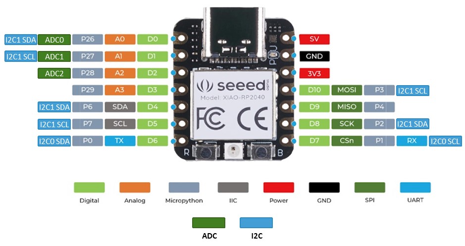
- The image above illustrates the pinout diagram of the XIAO-RP2040.
XIAO-RP2040 Schematic Diagram
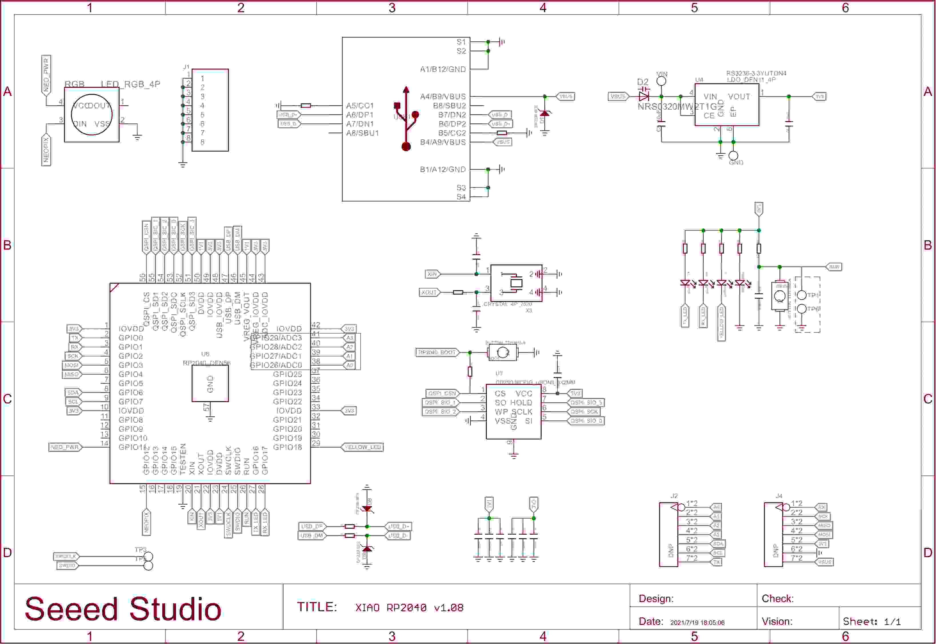
- The image above illustrates the schematic diagram of the XIAO-RP2040.
Quentorres Development Board
The Quentorres Development Board was initially developed by Quentin Bolsée and later reimagined by Adrián Torres for the XIAO-RP2040 microcontroller.
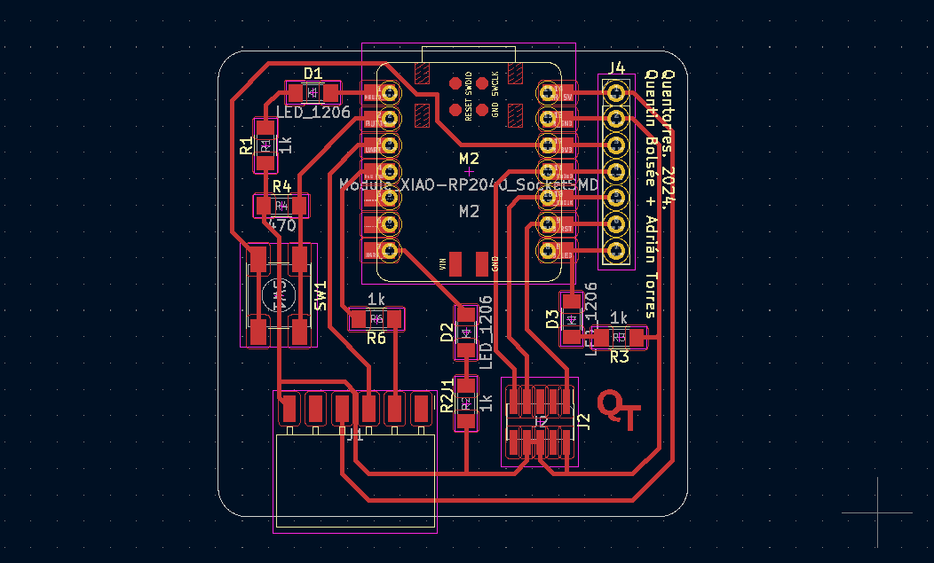
- The image below illustrates the PCB layout of the Quentorres Development Board.
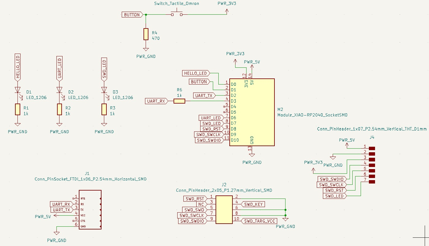
- The image below illustrates the schematic diagram of the Quentorres Development Board.
Programming the XIAO-RP2040 Board
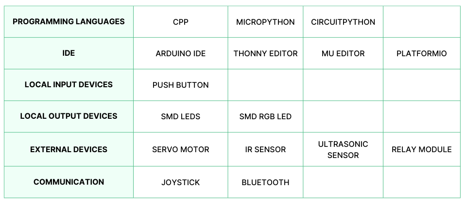
For programming the XIAO-Rp2040 board, I have tried to use multiple IDEs, such as:
- Arduino IDE
- Thonny Editor
- MU Editor
Arduino IDE
The Arduino IDE (Integrated Development Environment) is used to write the computer code and upload this code to the physical board. The Arduino IDE is very simple and this simplicity is probably one of the main reason Arduino became so popular.
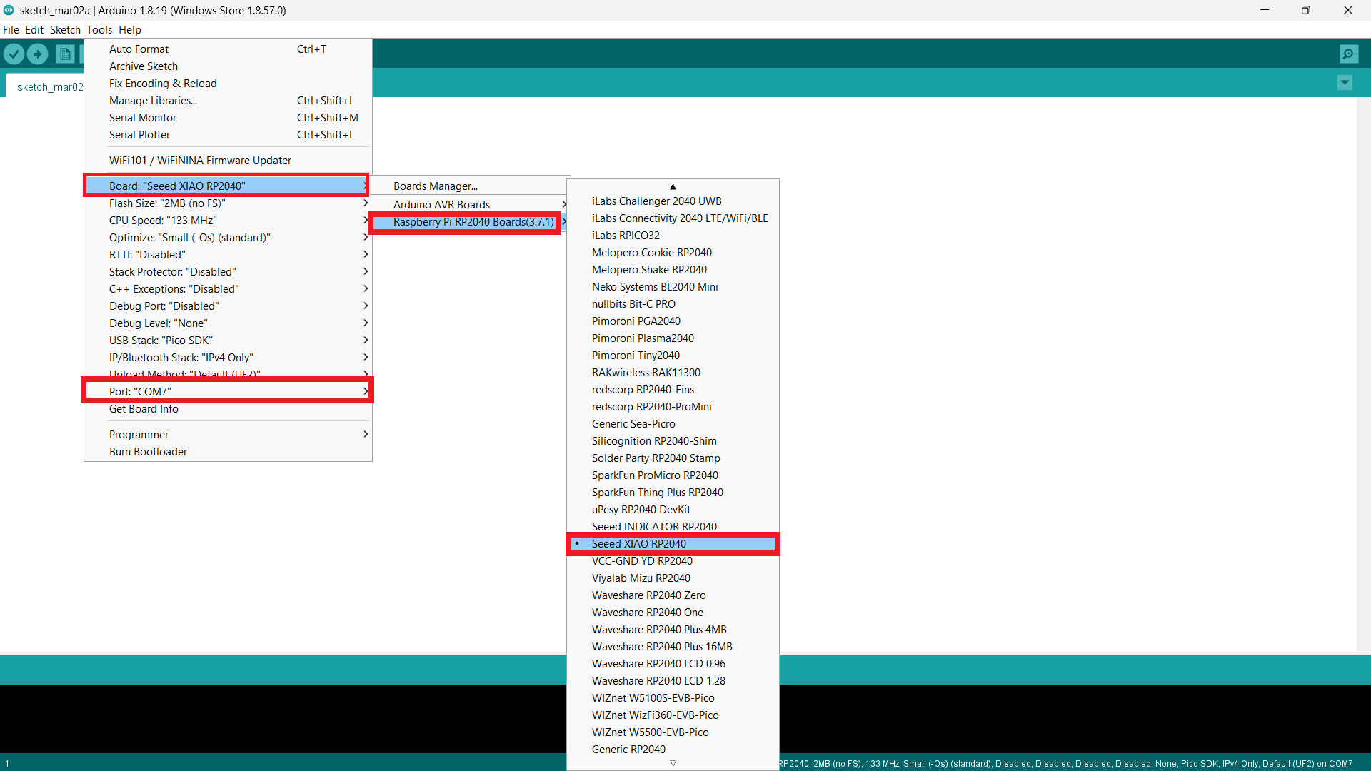
- Connect the XIAO board to the system.
- From “Tools” select “Board” then select “Raspberry Pi RP2040 Board”.
- To learn how to install the XIAO board in the Arduino IDE click here.
- Select “Seeed XIAO RP2040”.
Local LED
LED Blink Algorithm
Step 2: Set LED pin at 26 as output
Step 3: Turn on the LED for 1 second
Step 4: Turn off the LED for 1 second. Go to step 3.
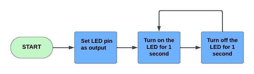
LED Blink Flow Chart
LED Blink Code
const int led1=26;          //assigned pin 26 to the constant integer variable led1
    void setup() {
      pinMode(led1, OUTPUT);    // set the led1 as output
    }
    void loop() {
      digitalWrite(led1, HIGH); // set the led1 to on
      delay(1000);              // delayed to 1 second
      digitalWrite(led1, LOW); // set the led1 to off
      delay(1000);             // delayed  to 1 second
    }
Local Push Button
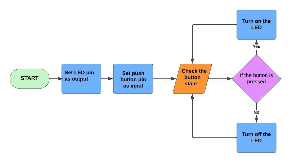
Push Button Based LED ON/OFF Algorithm
Step 2: Set the LED pins at 26, 0, and 1 as output.
Step 3: Set the button pin at 27 as input.
Step 4: Check the button state.
Step 5: If the button is pressed, turn on the LEDs. Go to step 4.
Step 6: If the button is released, turn off the LEDs. Go to step 4.
Push Button Based LED ON/OFF Flow Chart
Push Button Based LED ON/OFF Code 1
const int led1=26;            //assigned pin 26 to the constant integer variable led1
    const int led2=0;             //assigned pin 0 to the constant integer variable led2
    const int led3=1;             //assigned pin 1 to the constant integer variable led3
    const int but=27;             //assigned pin 27 to the constant integer variable but
    int buttonI=0;                //assigned value 0 to the integer variable buttonI //buttionI for button status
    void setup() {
      pinMode(led1, OUTPUT);     // set the led1 as output
      pinMode(led2, OUTPUT);     // set the led2 as output
      pinMode(led3, OUTPUT);     // set the led3 as output
      pinMode(but, INPUT);       // set the but as input
    }

    void loop() {
      buttonI = digitalRead(but);// read the button status
      if (buttonI==HIGH)
      {
        digitalWrite(led1, HIGH); // set the led1 on
        digitalWrite(led2, HIGH); // set the led2 on
        digitalWrite(led3, HIGH); // set the led3 on
      }
      else
      {
        digitalWrite(led1, LOW); // set the led1 off
        digitalWrite(led2, LOW); // set the led2 off
        digitalWrite(led3, LOW); // set the led3 off
      }

}Push Button Based LED ON/OFF Code 2
- The output of this code is the same as above, but here I used a function.
// Define the pin numbers for the LEDs and the button
const int led1 = 26; // Pin number for the first LED
const int led2 = 0; // Pin number for the second LED
const int led3 = 1; // Pin number for the third LED
const int but = 27; // Pin number for the button
int buttonI = 0; // Variable to store the button state
void setup() {
// Set the pinMode for each pin
pinMode(led1, OUTPUT); // Set the first LED pin as OUTPUT
pinMode(led2, OUTPUT); // Set the second LED pin as OUTPUT
pinMode(led3, OUTPUT); // Set the third LED pin as OUTPUT
pinMode(but, INPUT); // Set the button pin as INPUT
}
void loop() {
buttonI = digitalRead(but); // Read the state of the button
butfun(buttonI);// Call the function to handle button state
}
int butfun(int x) {
if (x == HIGH) {
// If the button state is HIGH (pressed), turn on all three LEDs
digitalWrite(led1, HIGH);
digitalWrite(led2, HIGH);
digitalWrite(led3, HIGH);
} else {
// If the button state is LOW (not pressed), turn off all three LEDs
digitalWrite(led1, LOW);
digitalWrite(led2, LOW);
digitalWrite(led3, LOW);
}
return 0; // Return 0 (this doesn't have a particular significance in this case)
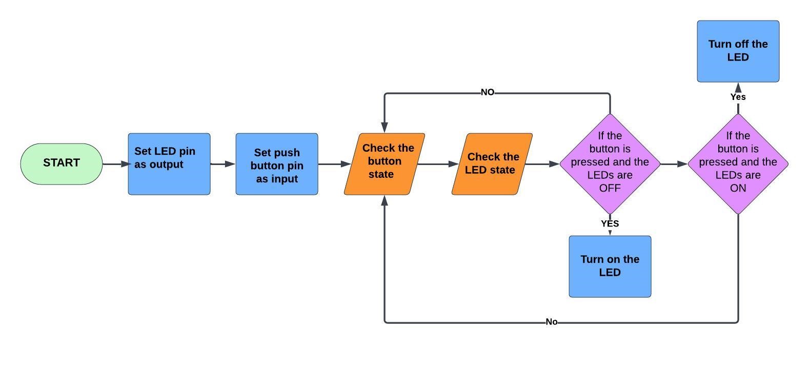
}Algorithm for Push Button based LED ON/OFF
Step 2: Set the LED pin at 26, 0, 1 as output, and set the button connected at pin 27 as input.
Step 3: Check the button state.
Step 4: Check the LED state.
Step 5: If the button is pressed and if the LEDs are off. Go to step 8.
Step 6: If the button is pressed and if the LEDs are on. Go to step 9.
Step 7: Go to step 3.
Step 8: Turn on the LEDs. Go to step 3.
Step 9: Turn off the LEDs. Go to step 3.
Push Button based LED ON/OFF Flow Chart
Push Button based LED ON/OFF Code using flag
- The code (using flag) below turns on the LED when the push button is pressed and only turns it off when the push button is pressed again.
const int led1 = 26; // Pin number for the first LED
    const int led2 = 0;  // Pin number for the second LED
    const int led3 = 1;  // Pin number for the third LED
    const int but = 27;  // Pin number for the push button
    int buttonI = 0;      // Variable to store the button state
    bool flag = false;    // Boolean flag to toggle the LEDs
    void setup() {
      pinMode(led1, OUTPUT); // Set the first LED pin as output
      pinMode(led2, OUTPUT); // Set the second LED pin as output
      pinMode(led3, OUTPUT); // Set the third LED pin as output
      pinMode(but, INPUT);   // Set the button pin as input
    }

    void loop() {
      buttonI = digitalRead(but); // Read the state of the button and store it in 'buttonI'

      if (buttonI == HIGH) {
        // If the button is pressed
        if (flag == false) {
          // If the flag is false, turn on all three LEDs
          flag = true;
          digitalWrite(led1, HIGH);
          digitalWrite(led2, HIGH);
          digitalWrite(led3, HIGH);
        } else {
          // If the flag is true, turn off all three LEDs
          flag = false;
          digitalWrite(led1, LOW);
          digitalWrite(led2, LOW);
          digitalWrite(led3, LOW);
        }
      }

      delay(300); // Introduce a delay to avoid rapid toggling and debounce the button
}- The code (without flag) below turns on the LED when the push button is pressed and only turns it off when the push button is pressed again.
const int led1=0;            // assigned pin 0 to integer variable led1
    const int led2=1;            // assigned pin 1 to integer variable led2
    const int led3=26;           // assigned pin 26 to integer variable led3
    const int but=27;            // assigned integer variable but as 27. "but" for button
    int button_state=0;          // assigned 0 to integer variable button_state
    int led_state=0;             // assigned 0 to integer variable "led_state"
    void setup() {
      pinMode(led1,OUTPUT);      // set the led1 as output
      pinMode(led2,OUTPUT);      // set the led2 as output
      pinMode(led3,OUTPUT);      // set the led3 as output
      pinMode(but,INPUT);        // set the but as input
    }
    void loop() {
      button_state= digitalRead(but); // read the digital value of but and stored to button_state

      if (button_state==1) // Check if the button is pressed
      {
        if (led_state==0) // Check if the led is off
        {
          digitalWrite(led1,HIGH); // Turn on led1
          digitalWrite(led2,HIGH); // Turn on led2
          digitalWrite(led3,HIGH); // Turn on led3
          led_state=1;             // set the led status to on
        }
        else
        {
          digitalWrite(led1,LOW); //Turn off the led1
          digitalWrite(led2,LOW); //Turn off the led2
          digitalWrite(led3,LOW); //Turn off the led3
          led_state=0;            // set the led status to off
        }
      }
      delay(300);                 //delay is for debouncing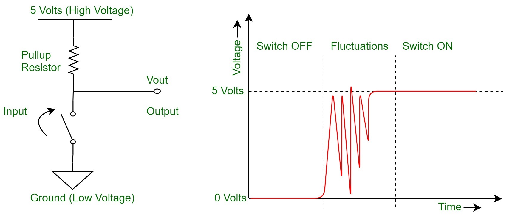
}Switch Debounce in Digital Circuits
- Switch bounce is a phenomenon that occurs in digital circuits when a mechanical switch is pressed or released. When a switch changes its state, it doesn't make an instantaneous transition from one state to another. Instead, during the transition, the electrical contacts within the switch can make momentary, rapid contact and separation, causing the electrical signal to fluctuate temporarily.
- This rapid bouncing of the switch contacts can result in multiple open and close transitions within a very short time, typically in the range of milliseconds.
- To mitigate switch bounce, designers often use techniques such as debouncing circuits.
 https://www.geeksforgeeks.org/switch-debounce-in-digital-circuits/
 https://www.youtube.com/watch?v=jYOYgU2vlSE
const int led1 = 0;          // assigned pin 0 to integer variable led1
    const int led2 = 1;          // assigned pin 1 to integer variable led2
    const int led3 = 26;         // assigned pin 26 to integer variable led3
    const int but = 27;          // assigned integer variable but as 27. "but" for button
    int button_state = 0;        // assigned 0 to integer variable button_state
    int led_state = 0;           // assigned 0 to integer variable "led_state"
    bool pressed = false;        // assigned false to boolean variable pressed
    void setup() {
      pinMode(led1, OUTPUT);     // set the led1 as output
      pinMode(led2, OUTPUT);     // set the led2 as output
      pinMode(led3, OUTPUT);     // set the led3 as output
      pinMode(but, INPUT);       // set the but as input
    }
    void loop() {
      button_state = digitalRead(but); // read the digital value of but and stored to button_state
      if (button_state == HIGH)       // check if the button is pressed
      {
        if (pressed == false)         // check if pressed flag is false
        {
          if (button_state == 1)   // Check if the button is pressed
          {
            if (led_state == 0)        // Check if the led is off
            {
              digitalWrite(led1, HIGH); // Turn on led1
              digitalWrite(led2, HIGH); // Turn on led2
              digitalWrite(led3, HIGH); // Turn on led3
              led_state = 1;           // set the led status to on
            }
            else
            {
              digitalWrite(led1, LOW); //Turn off the led1
              digitalWrite(led2, LOW); //Turn off the led2
              digitalWrite(led3, LOW); //Turn off the led3
              led_state = 0;          // set the led status to off
            }
          }
          delay(300);                 //delay is for debouncing
          pressed = true;             //set the pressed flag as true
        }
      } else {
        pressed = false;             //set the pressed boolean as false
        delay(50);                   //set delay for 50 milli second
      }
}Serial Communication
Serial communication is a method of sending and receiving data between two or more electronic devices, one bit at a time over a single communication line.
- Data is being sent in "series"
The most common types of serial communication on Arduino are UART (Universal Asynchronous Receiver/Transmitter) and USB (Universal Serial Bus).
Here are the key components and aspects of serial communication in Arduino:
- Serial Library: Arduino provides a built-in Serial library that simplifies the implementation of serial communication. This library includes functions for sending and receiving data over the serial port.
- Hardware Serial (UART): Most Arduino boards have a built-in UART (Universal Asynchronous Receiver/Transmitter) that allows serial communication. The primary functions for UART communication are Serial.begin(), Serial.print(), and Serial.read().
| Serial.begin (baudrate): | Initializes the serial communication with a specific baud rate (data transfer rate in bits per second). |
| Serial.print (data): | Sends data (characters, numbers, etc.) to the serial port. |
| Serial.read(): | Reads incoming data from the serial port. |
https://www.youtube.com/watch?v=tpEo5AOSSkg
const int led1 = 0;          // assigned pin 0 to integer variable led1
    const int led2 = 1;          // assigned pin 1 to integer variable led2
    const int led3 = 26;         // assigned pin 26 to integer variable led3
    const int but = 27;          // assigned integer variable but as 27. "but" for button
    int button_state = 0;        // assigned 0 to integer variable button_state
    int led_state = 0;           // assigned 0 to integer variable "led_state"
    bool pressed = false;        // assigned false to boolean variable pressed
    void setup() {
      Serial.begin(9600);
      pinMode(led1, OUTPUT);     // set the led1 as output
      pinMode(led2, OUTPUT);     // set the led2 as output
      pinMode(led3, OUTPUT);     // set the led3 as output
      pinMode(but, INPUT);       // set the but as input
      Serial.print("week 06");
    }
    void loop() {
      button_state = digitalRead(but); // read the digital value of but and stored to button_state
      if (button_state == HIGH)       // check if the button is pressed
      {
        Serial.println("button pressed");
        if (pressed == false)         // check if pressed flag is false
        {
          if (button_state == 1)   // Check if the button is pressed
          {
            if (led_state == 0)        // Check if the led is off
            {
              Serial.println("LED is ON");
              digitalWrite(led1, HIGH); // Turn on led1
              digitalWrite(led2, HIGH); // Turn on led2
              digitalWrite(led3, HIGH); // Turn on led3
              led_state = 1;           // set the led status to on
            }
            else
            {
              Serial.println("LED is OFF");
              digitalWrite(led1, LOW); //Turn off the led1
              digitalWrite(led2, LOW); //Turn off the led2
              digitalWrite(led3, LOW); //Turn off the led3
              led_state = 0;          // set the led status to off
            }
          }
          delay(300);                 //delay is for debouncing
          pressed = true;             // assign the pressed flag to true
        }
      } else {
        pressed = false;              // set the pressed flag to false
        delay(50);                    // applied 50 milli second delay
      }
    }
- To open the serial monitor, click on the magnifying glass icon on the right side of the Arduino IDE.
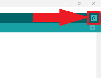
- The image below shows the serial monitor output.
Recursive Function
A recursive function is a function that calls itself during its execution. In other words, it's a function that solves a problem by solving smaller instances of the same problem. The process of solving a problem in terms of smaller instances is known as recursion.
- Base Case(s): These are the conditions under which the function stops calling itself and returns a result directly. The base case(s) prevent the recursion from continuing indefinitely.
- Recursive Case(s): These are the conditions under which the function calls itself to solve a smaller instance of the same problem. The recursive case(s) break down the original problem into simpler sub-problems.
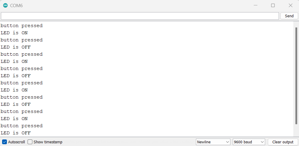
For this time, I decided to use ChatGPT to code according to my desired output, and here is the prompt.
const int buttonPin = 27;      // Pin number for the push button
    const int ledPins[] = {0, 1, 26};  // Pin numbers for three LEDs
    int currentLed = 0;            // Index of the currently lit LED
    int buttonState = LOW;         // Current state of the button
    int lastButtonState = LOW;     // Previous state of the button
    unsigned long lastDebounceTime = 0;  // Last time the button was pressed (milliseconds)
    unsigned long debounceDelay = 50;    // Delay time to debounce the button

    void setup() {
      for (int i = 0; i < 3; i++) {
        pinMode(ledPins[i], OUTPUT);   // Set LED pins as output
      }
      pinMode(buttonPin, INPUT);   // Set button pin as input
    }

    void loop() {
      int reading = digitalRead(buttonPin);  // Read the state of the button

      if (reading != lastButtonState) {
        lastDebounceTime = millis();  // Update debounce time when the button state changes
      }

      if ((millis() - lastDebounceTime) > debounceDelay) {
        if (reading != buttonState) {
          buttonState = reading;  // Update button state if debounced
          if (buttonState == HIGH) {
            toggleLED();  // Start the recursive LED toggle function
          }
        }
      }

      lastButtonState = reading;  // Save the current button state
    }

    void toggleLED() {
      digitalWrite(ledPins[currentLed], LOW);  // Turn off the current LED

      currentLed = (currentLed + 1) % 3;  // Move to the next LED index (circular increment)

      digitalWrite(ledPins[currentLed], HIGH);  // Turn on the new current LED
}Thonny Editor
Thonny is a free, open-source Python Integrated Development Environment (IDE). It's designed for beginners, with a basic user interface and Python 3 pre-installed. Thonny has a built-in debugger, step-by-step expression evaluation, and call stack visualization. It also helps users step into a function call by providing details about local variables and displaying the code pointer. Thonny is available on Windows, macOS, and Linux. It can be installed as a binary bundle with the latest Python interpreter, a pip-installable package, or the operating-system package manager on Debian, Raspberry Pi, Ubuntu, and Fedora.
Programming XIAO in MicroPython
The XIAO is a compact development board based on the ATSAMD21G18 microcontroller, and MicroPython is a lightweight implementation of Python 3 for microcontrollers.
MicroPython
MicroPython is a lean and efficient implementation of the Python 3 programming language that is designed to run on microcontrollers and constrained environments. It brings the ease and expressiveness of Python to the embedded systems world, making it more accessible for developers to work with microcontrollers and other resource-constrained devices.
 https://realpython.com/micropython/
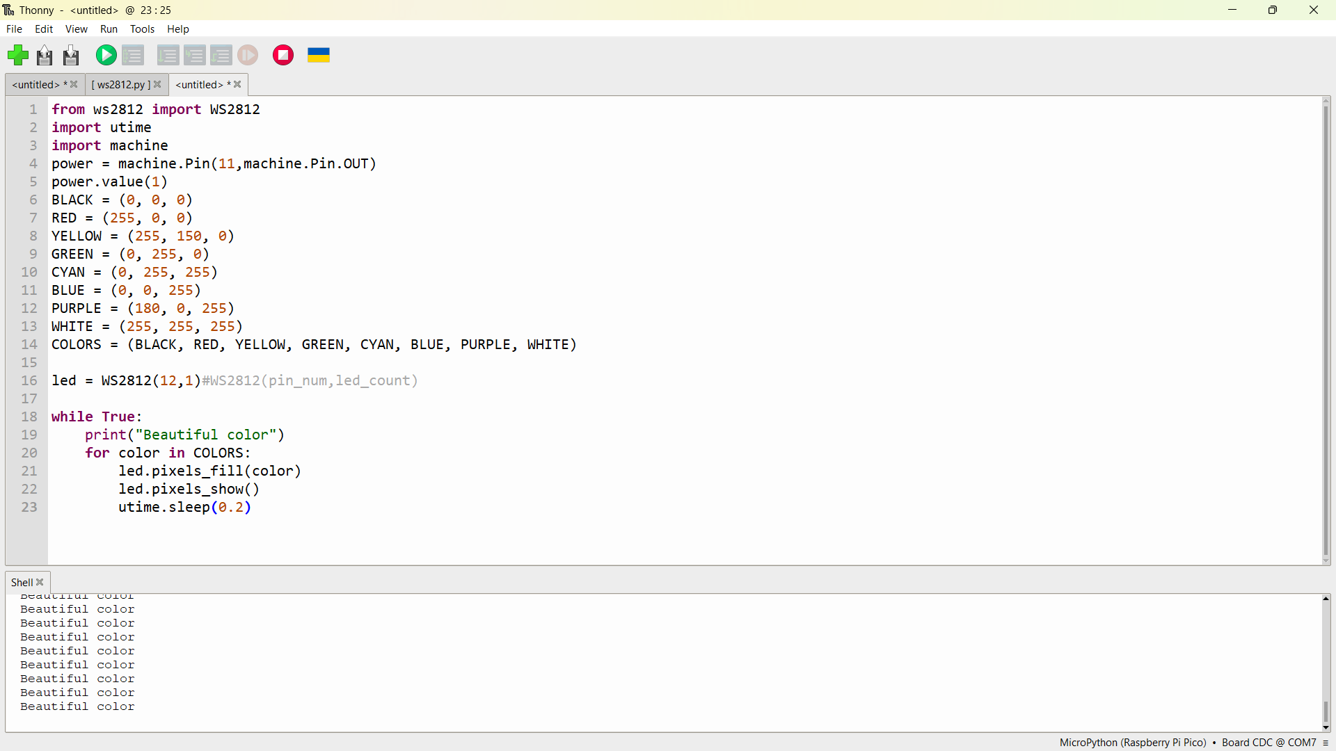
MicroPython RGB LED Code
# Import the WS2812 class from the ws2812 module
    from ws2812 import WS2812

    # Import the utime module for sleep functions and the machine module for hardware control
    import utime
    import machine

    # Set up a pin (pin 11) to control the power of the WS2812 LEDs
    power = machine.Pin(11, machine.Pin.OUT)
    power.value(1)  # Turn on the power to the WS2812 LEDs

    # Define RGB color values for convenience
    BLACK = (0, 0, 0)
    RED = (255, 0, 0)
    YELLOW = (255, 150, 0)
    GREEN = (0, 255, 0)
    CYAN = (0, 255, 255)
    BLUE = (0, 0, 255)
    PURPLE = (180, 0, 255)
    WHITE = (255, 255, 255)

    # Create a tuple of color values for iteration
    COLORS = (BLACK, RED, YELLOW, GREEN, CYAN, BLUE, PURPLE, WHITE)

    # Initialize the WS2812 object with pin 12 and 1 LED
    led = WS2812(12, 1)  # WS2812(pin_num, led_count)

    # Enter an infinite loop to continuously display colors
    while True:
        print("Beautiful color")

        # Iterate through each color in the COLORS tuple
        for color in COLORS:
            # Fill all LEDs with the current color
            led.pixels_fill(color)

            # Update the physical LEDs to display the filled color
            led.pixels_show()

            # Pause for a short duration to observe the color (0.2 seconds in this case)
            utime.sleep(0.2)
Mu Editor
Mu Editor is an open-source Python editor specifically designed for beginners and educators, especially those who are learning or teaching programming with the microcontroller platform CircuitPython. The editor is developed with simplicity in mind, providing an easy-to-use environment for writing, editing, and running Python code on microcontroller boards.
Programming XIAO in CircuitPython
CircuitPython is a programming language and a lightweight version of Python designed specifically for microcontrollers and small embedded systems. It is an open-source project developed by Adafruit Industries to make programming microcontrollers more accessible and user-friendly, especially for beginners and those new to electronics.
 https://learn.adafruit.com/welcome-to-circuitpython/circuitpython-essentials
CircuitPython LED Blink Code
"""Example for Pico. Blinks the built-in LED."""
    import time
    import board
    import digitalio

    led = digitalio.DigitalInOut(board.LED)
    led.direction = digitalio.Direction.OUTPUT

    while True:
        led.value = True
        time.sleep(0.5)
        led.value = False
        time.sleep(0.5)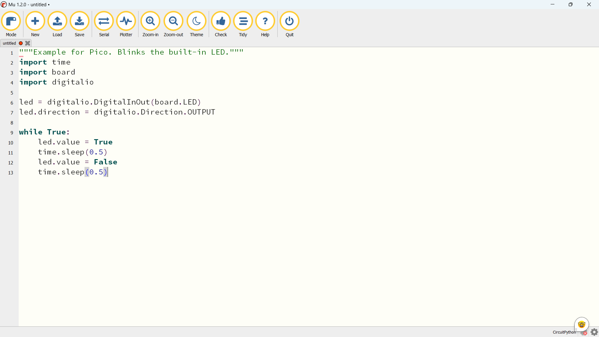
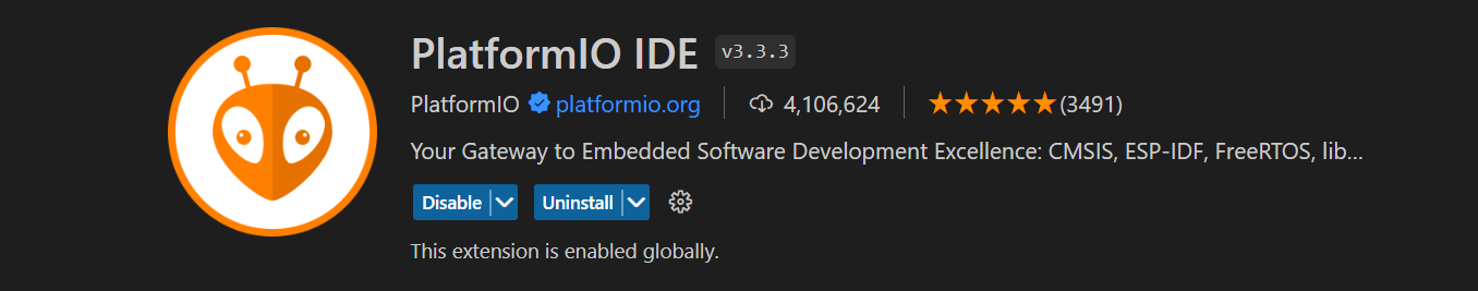
PlatformIo
PlatformIO is a free, open-source, multi-framework, cross-platform, cross-architecture, professional IDE tool. PlatformIO aims to simplify the process of building, testing, and deploying code for embedded systems and IoT devices.
Key features of PlatformIO include:
- Cross-platform Development: PlatformIO supports multiple operating systems, including Windows, macOS, and Linux, making it a cross-platform development environment.
- Built-in Package Manager: PlatformIO includes a built-in package manager that simplifies the installation and management of libraries, frameworks, and toolchains needed for specific hardware platforms.
- Integrated Development Environment (IDE) Integration: PlatformIO can be integrated with popular IDEs such as Visual Studio Code, Atom, and Eclipse. This integration enhances the development experience with features like code autocompletion, syntax highlighting, and debugging.
- Built-in Testing Framework: The platform includes a testing framework for automated unit testing, which is essential for ensuring the reliability and correctness of embedded systems code.
- Device Management: PlatformIO provides tools for managing connected devices, making it easier to upload firmware and monitor the status of embedded devices.
How to install PlatformIo in VS code
- Open VS code
- From the Extension bar search for “PlatformIo IDE”
- Click on Install
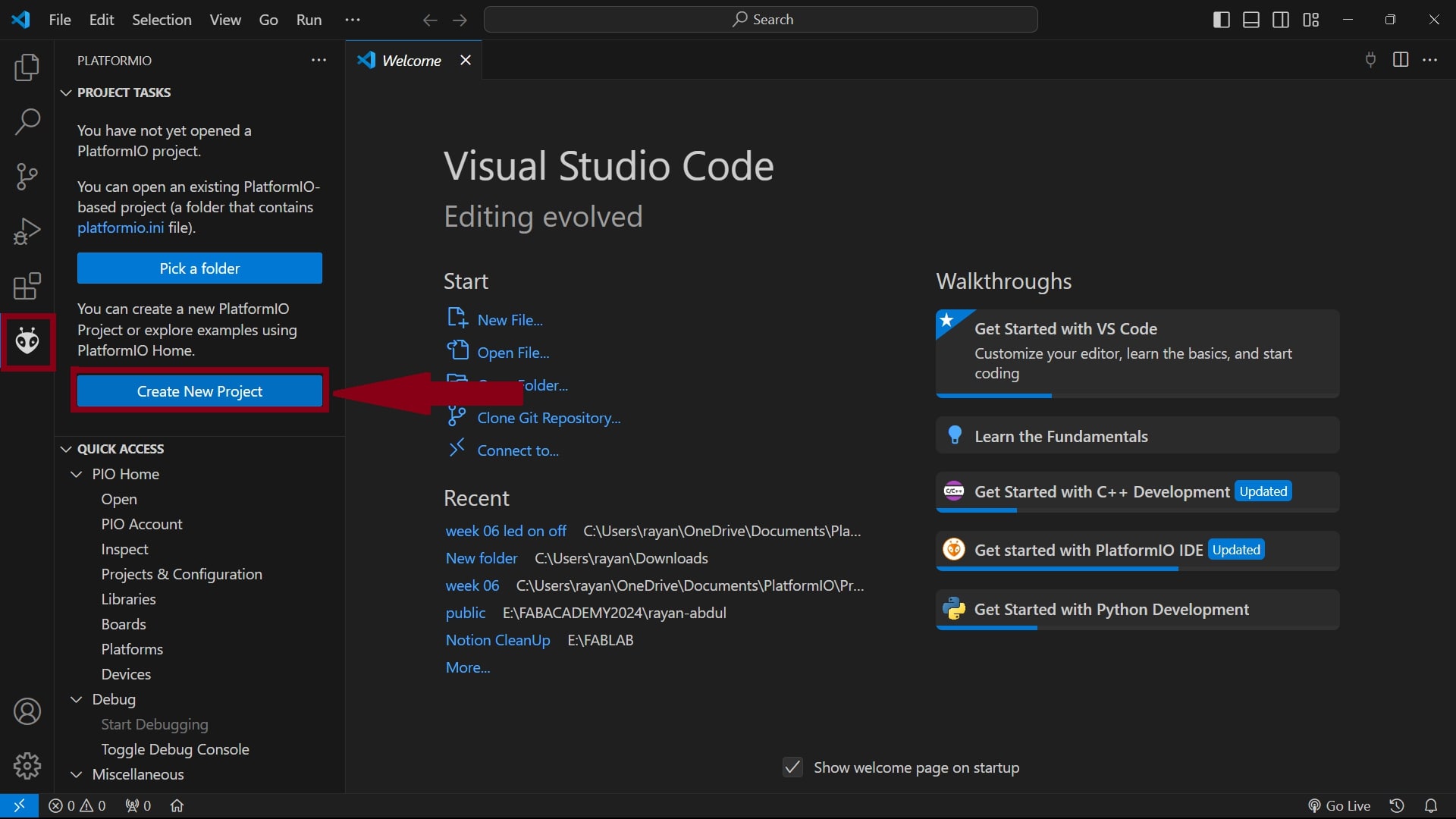
Programming XIAO-RP2040 using PlatformIo
- After installing PlatformIo, an alien icon will appear on the vertical tab. Click on it.
- Select “Create New Project”
- Select “New Project” button.
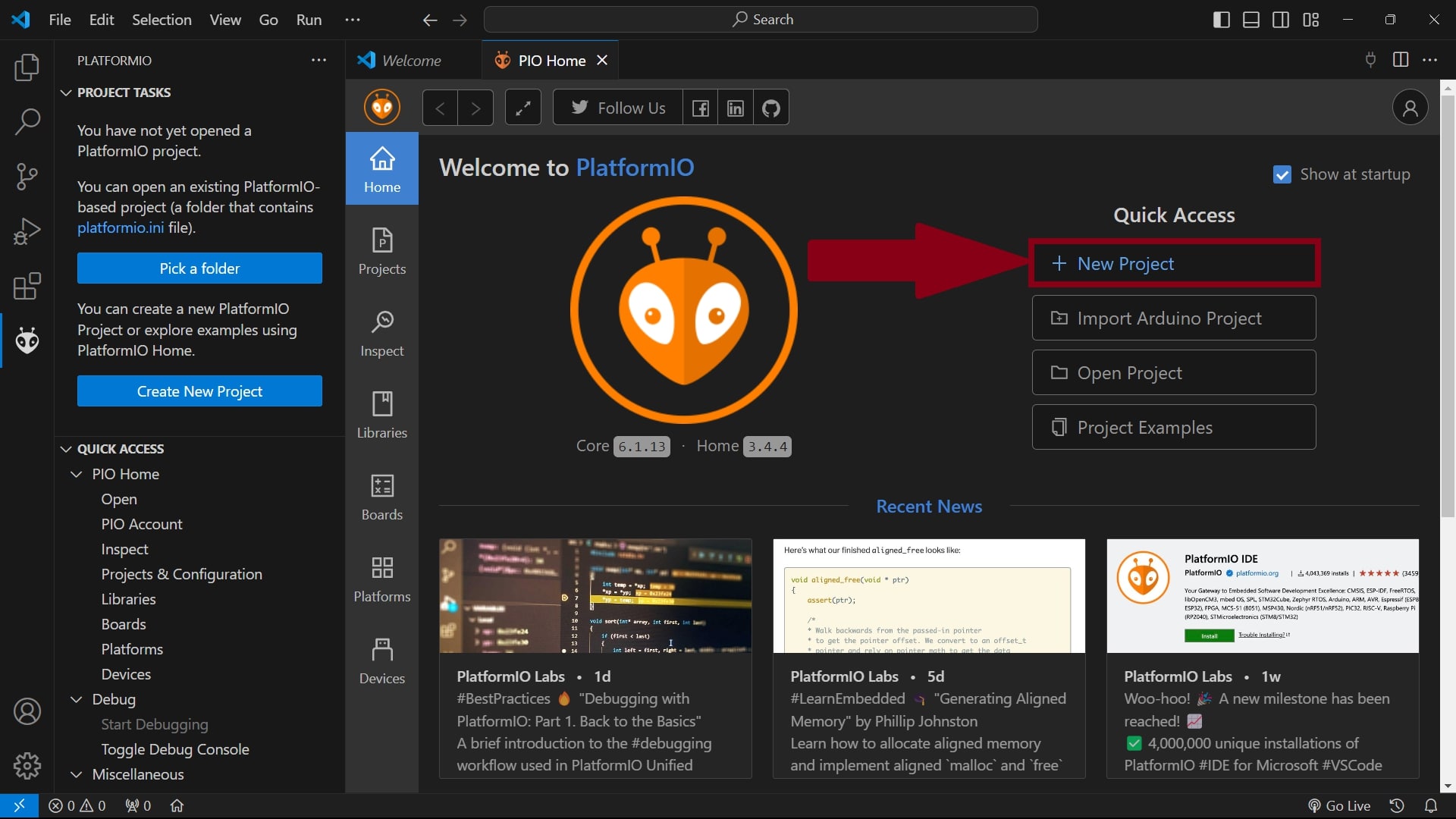
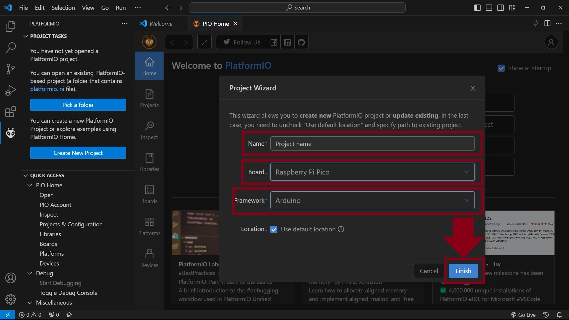
- A project wizard will appear.
- From the board list, select “Raspberry Pi Pico”.
- From the framework, select “Arduino”.
- Type desired project name.
- Click on “Finish”.
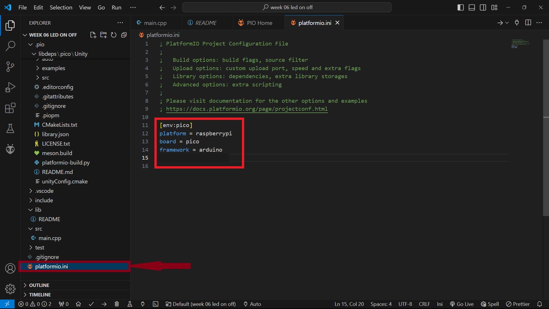
- Select the “platformio.ini” file from the file tree to verify the selected board options.
- Select the “main.cpp” to program the XIAO-RP2040 board.
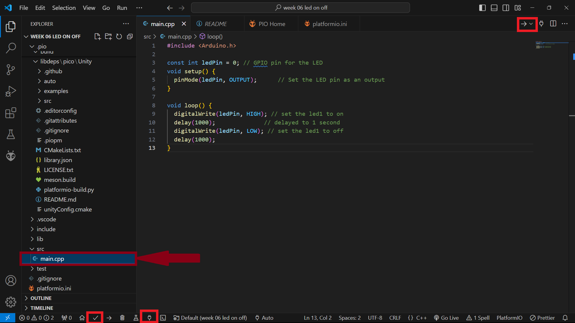
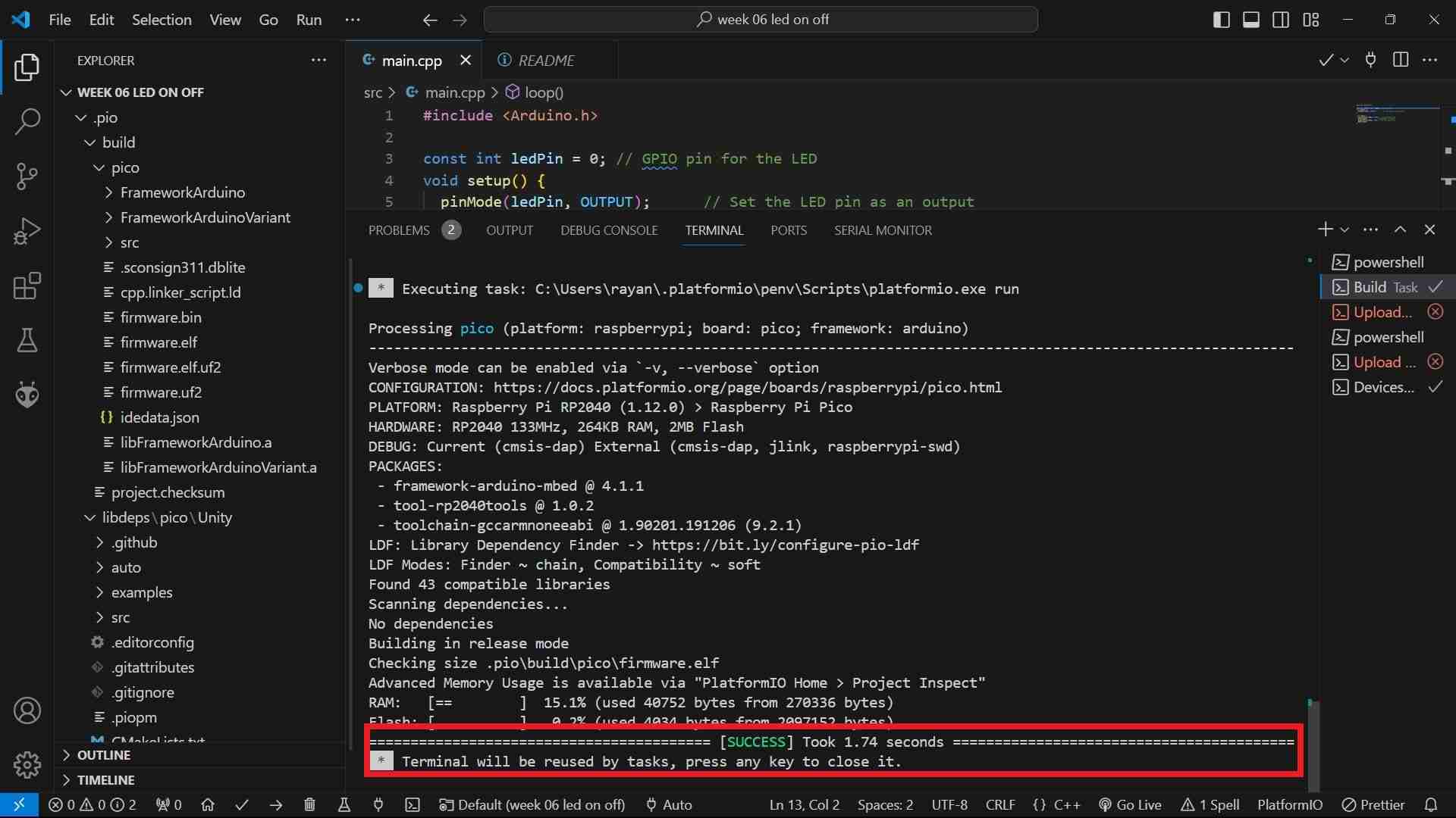
- In order to test programming the board using the platformIo IDE, I decided to upload the blink code.
#include <Arduino.h>

    const int ledPin = 0; // GPIO pin for the LED
    void setup() {
      pinMode(ledPin, OUTPUT);      // Set the LED pin as an output
    }

    void loop() {
      digitalWrite(ledPin, HIGH); // set the led1 to on
      delay(1000);              // delayed to 1 second
      digitalWrite(ledPin, LOW); // set the led1 to off
      delay(1000);
}- In PlatformIO, "build" and "upload" are two distinct processes in the development workflow.
- The "build" process involves compiling your source code and creating the binary executable file that can run on your target device (microcontroller or development board).
- The "upload" process involves transferring the compiled binary file from your computer to the actual hardware device (microcontroller or development board) so that it can run the code.
- The build and upload option can be selected by selecting from the top right corner tick mark or the bottom left corner tick mark.
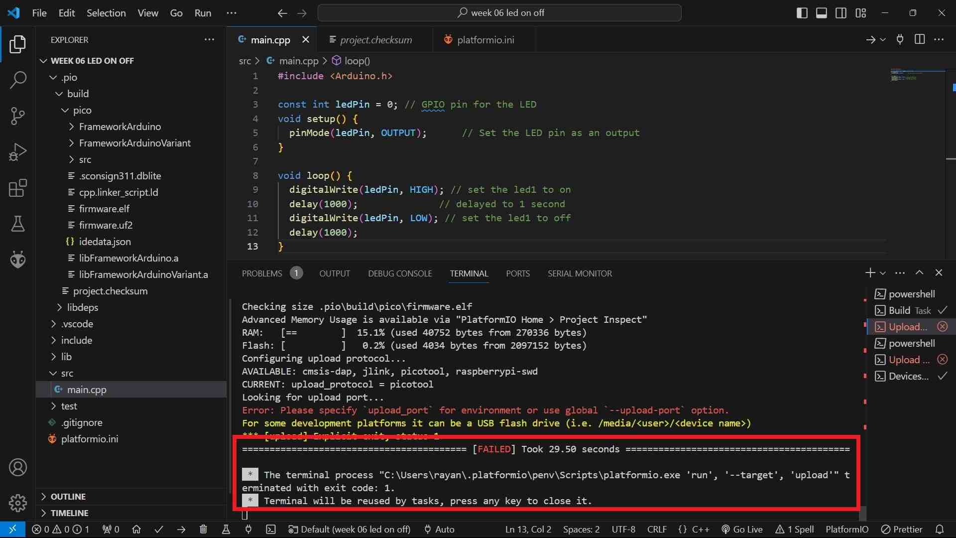
- I decided to show this to my instructor, and he tried to upload the code in a different way.
- Press the boot button on the XIAO board, and then press the reset button without leaving the boot button. Then a folder will open up. Drag and drop the “firmware.uf2” file to that folder.
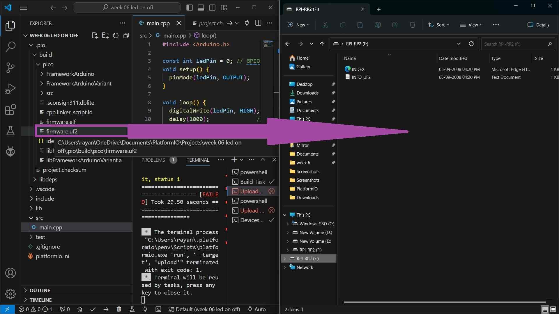
- It worked 🙂🙂🙂.
Final Result
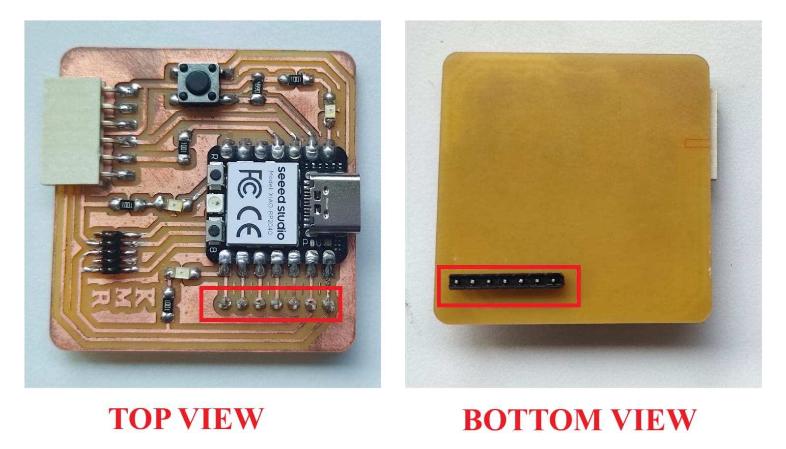
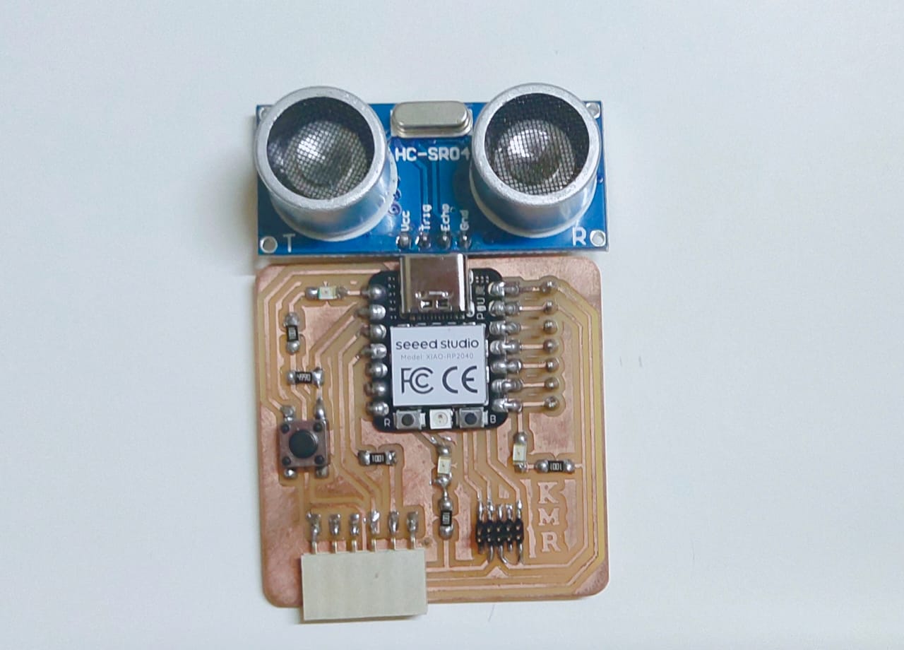
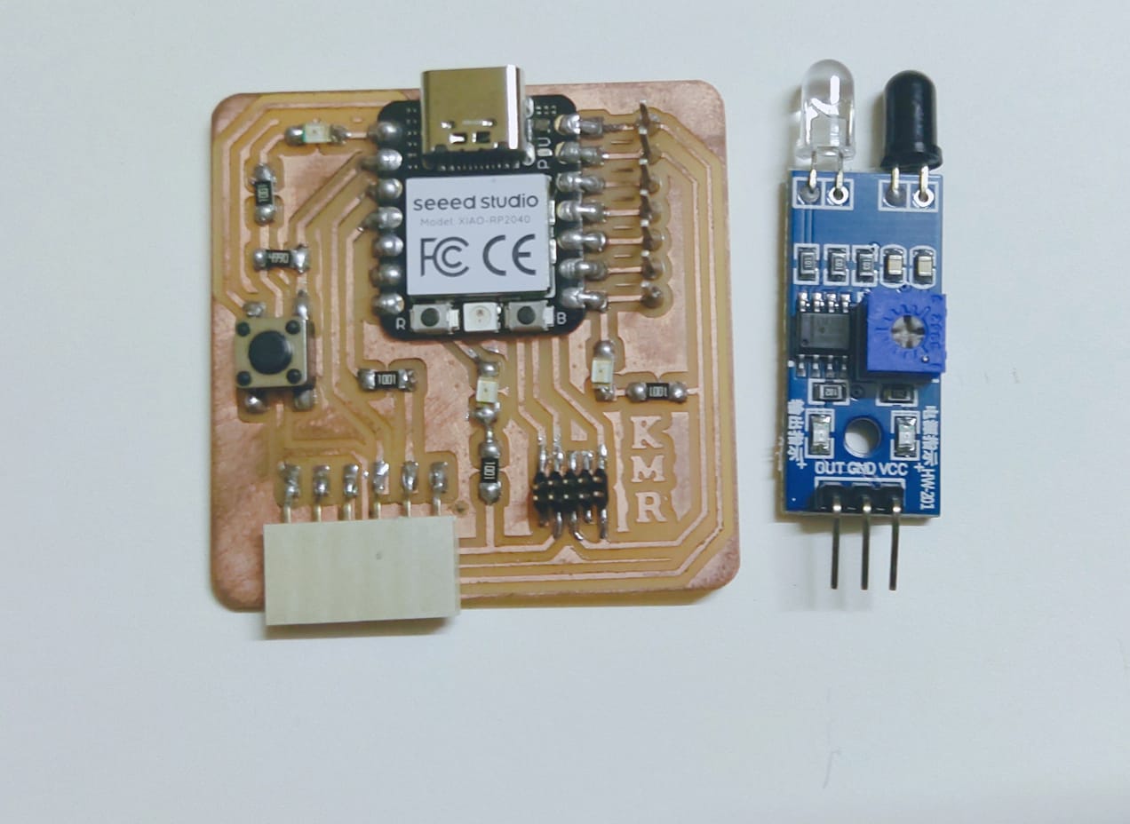
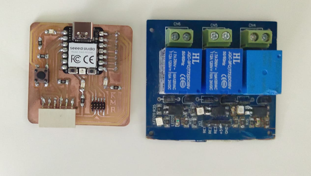
External Components
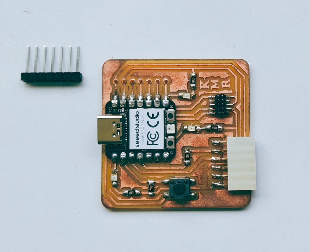
- The photo below shows the top view and bottom view of the development board after soldering the header pins.
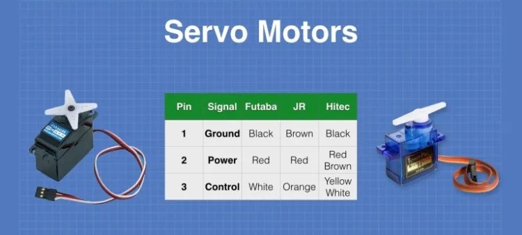
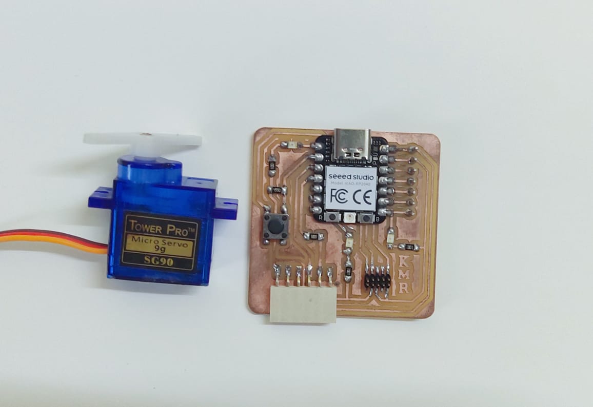
Servo Motor
A servo motor, or servo, is an electronic device that rotates or pushes parts of a machine with precision. Servos are used to control the angular or linear position, velocity, and acceleration of a mechanical system.
https://youtu.be/1WnGv-DPexc?si=k0_ni82EokoGcX_s
Here's a general overview of how a servo motor works:
- Motor:
- The heart of the servo motor is a DC motor, often a brushed or brushless motor.
- The motor provides the necessary rotational force to drive the output shaft.
- Position Sensor:
- A position sensor, such as a potentiometer or an encoder, is typically attached to the output shaft of the motor.
- The position sensor continuously measures the current position of the shaft.
- Control Circuit:
- The control circuit is responsible for processing the input signals and comparing them with the actual position feedback from the position sensor.
- It generates an error signal based on the difference between the desired position and the actual position.
- Amplifier:
- The error signal is then amplified to produce a control signal with sufficient power to drive the motor.
- Gear Mechanism:
- Many servo motors have a gear mechanism that reduces the speed of the motor and increases the torque at the output shaft. This helps in achieving higher precision.
- Output Shaft:
- The output shaft of the servo motor rotates in response to the control signal applied by the amplifier.
- As the output shaft rotates, it changes the position of the device or system it is controlling.
- Feedback Loop:
- The position sensor continuously provides feedback to the control circuit.
- The control circuit adjusts the control signal based on the feedback, reducing the error until the desired position is reached.
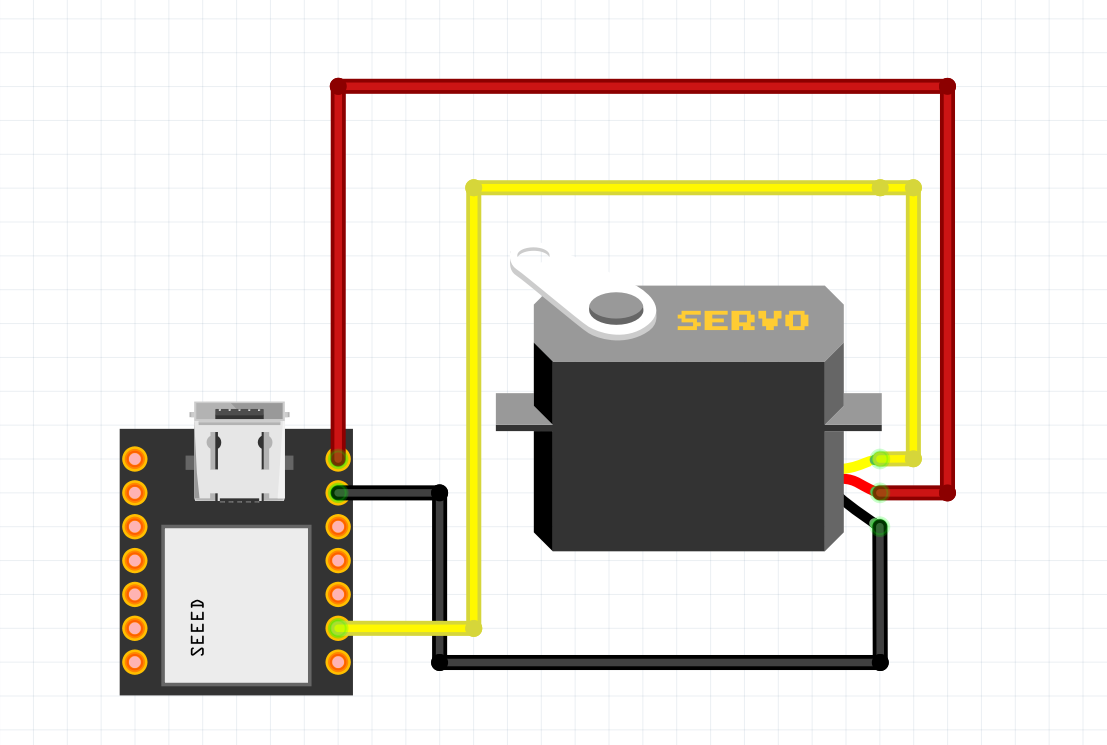
#include <Arduino.h>
    #include <Servo.h>

    Servo servoMotor; // Create a Servo object to control a servo motor

    void setup() {
      servoMotor.attach(2); // Attach the servo to GPIO pin 2
    }

    void loop() {
      servoMotor.write(180); // Set the servo position to 180 degrees
      delay(1000);          // Wait for 1 second

      servoMotor.write(90);  // Set the servo position to 90 degrees
      delay(1000);          // Wait for 1 second

      servoMotor.write(0);   // Set the servo position to 0 degrees
      delay(1000);          // Wait for 1 second
    }
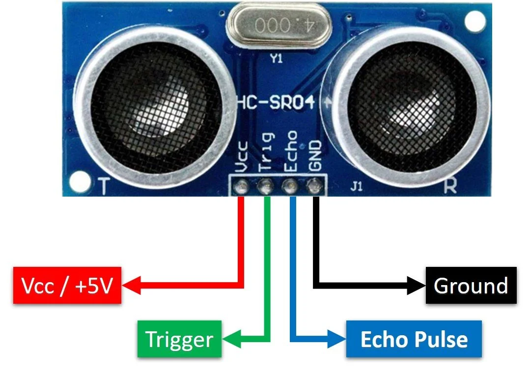
HC-SR04 Ultrasonic Sensor
The HC-SR04 is an ultrasonic distance measuring sensor that uses sonar to measure non-contact distances. It's made up of two ultrasonic transducers: a transmitter that emits ultrasonic sound pulses and a receiver that listens for reflected waves. The sensor works by measuring the time it takes for the echo to return to calculate the distance to an object.
https://youtu.be/6F1B_N6LuKw?si=OTEbNqznQuxK502a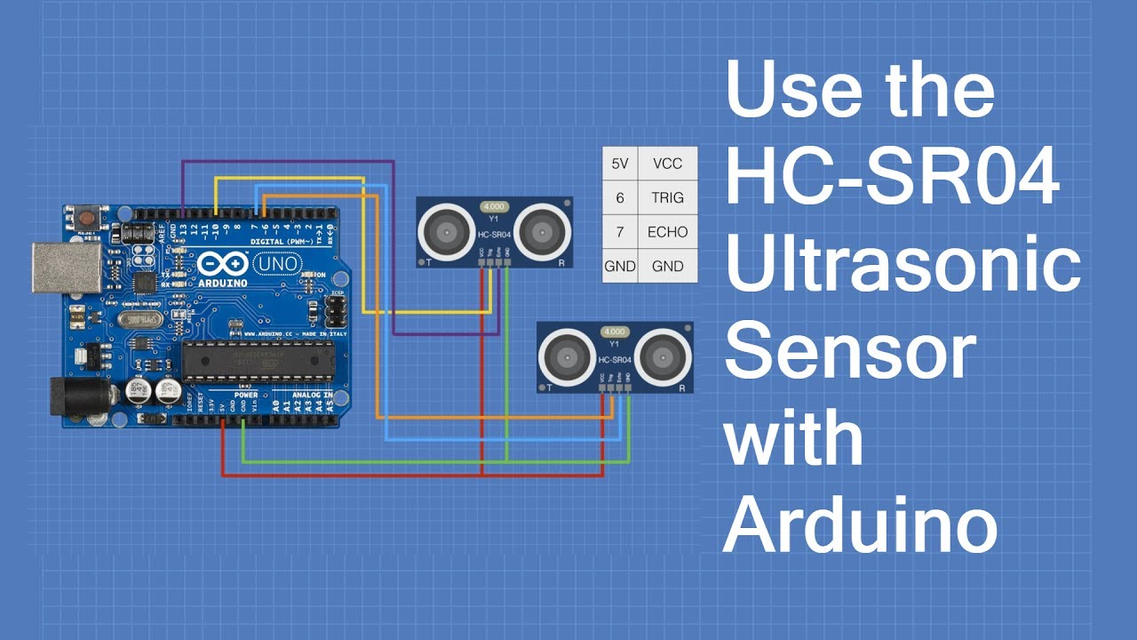
general overview of how the HC-SR04 ultrasonic sensor works:
- Ultrasonic Transmitter:
- The sensor has an ultrasonic transmitter (also called a transducer) that emits short pulses of ultrasonic sound waves.
- Ultrasonic Receiver:
- The sensor also has an ultrasonic receiver that detects the echo of the transmitted sound waves.
- Trigger Pulse:
- To start the measurement process, a microcontroller or any control system sends a short pulse (typically 10 microseconds) to the trigger pin of the sensor.
- Ultrasonic Pulse Emission:
- The HC-SR04 sensor emits a burst of ultrasonic waves (sound waves with a frequency above the human hearing range).
- Traveling to the Target:
- The emitted ultrasonic waves travel through the air until they encounter an object.
- Reflection from the Object:
- When the ultrasonic waves hit an object, they get reflected back towards the sensor.
- Echo Reception:
- The ultrasonic receiver on the HC-SR04 detects the reflected waves as an echo.
- Time Measurement:
- The time taken for the ultrasonic waves to travel to the object and back is measured. This time is often referred to as the "time of flight."
- Distance Calculation:
- The distance (D) between the sensor and the object can be calculated using the formula:
D = (Time of Flight * Speed of Sound) / 2- The speed of sound is approximately 343 meters per second (at room temperature).
- The distance (D) between the sensor and the object can be calculated using the formula:
- Output:
- The HC-SR04 then provides the distance measurement as an output signal, typically in centimeters or inches.
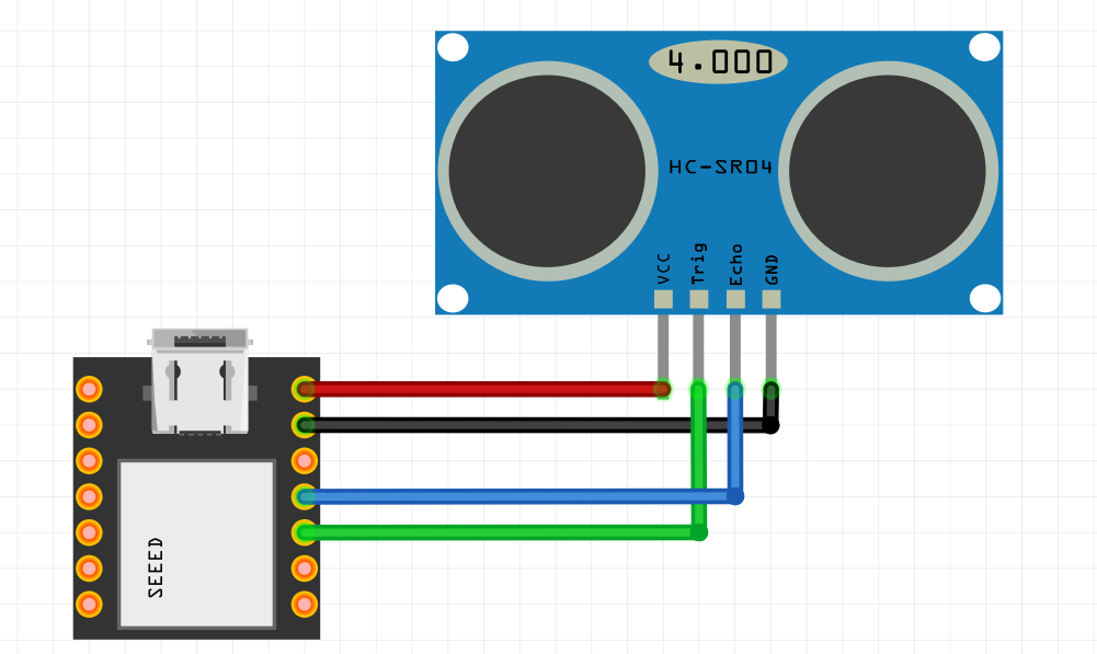
#include <Arduino.h>
const int triggerPin = 4p; // GPIO pin for the ultrasonic sensor trigger
const int echoPin = 3; // GPIO pin for the ultrasonic sensor echo
void setup() {
Serial.begin(9600);
pinMode(triggerPin, OUTPUT);
pinMode(echoPin, INPUT);
}
void loop() {
// Trigger ultrasonic sensor by sending a pulse
digitalWrite(triggerPin, LOW);
delayMicroseconds(2);
digitalWrite(triggerPin, HIGH);
delayMicroseconds(10);
digitalWrite(triggerPin, LOW);
// Measure the duration of the echo pulse
unsigned long duration = pulseIn(echoPin, HIGH);
// Calculate the distance in centimeters
float distance = (duration * 0.0343) / 2;
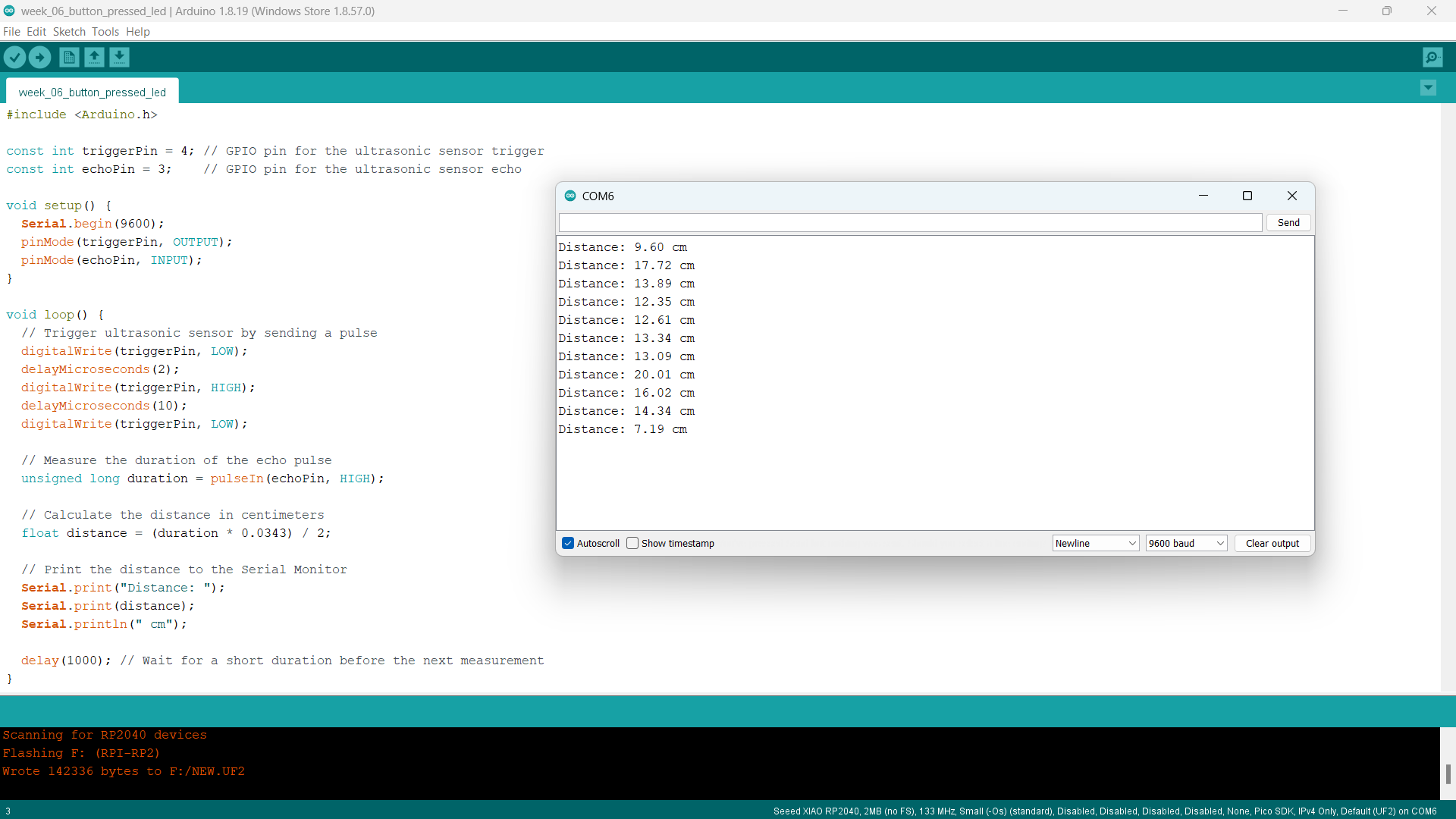
// Print the distance to the Serial Monitor
Serial.print("Distance: ");
Serial.print(distance);
Serial.println(" cm");
delay(1000); // Wait for a short duration before the next measurement
}
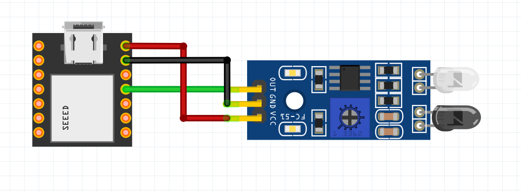
HW-201 Infrared (IR) Sensor
The HW-201 is an infrared (IR) sensor module that can detect objects. It has a detection range of 2-30 cm, depending on the surface.
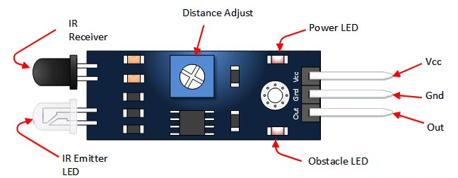
Components of an IR Sensor Module:
- Infrared Emitter (LED): The module includes an infrared light-emitting diode (LED) that emits infrared light. The emitted light is usually in the near-infrared spectrum, which is not visible to the human eye.
- Photodetector (Photodiode or Phototransistor): The module also contains a photodetector, which can be either a photodiode or a phototransistor. This component detects the infrared light that is reflected or emitted by objects in its vicinity.
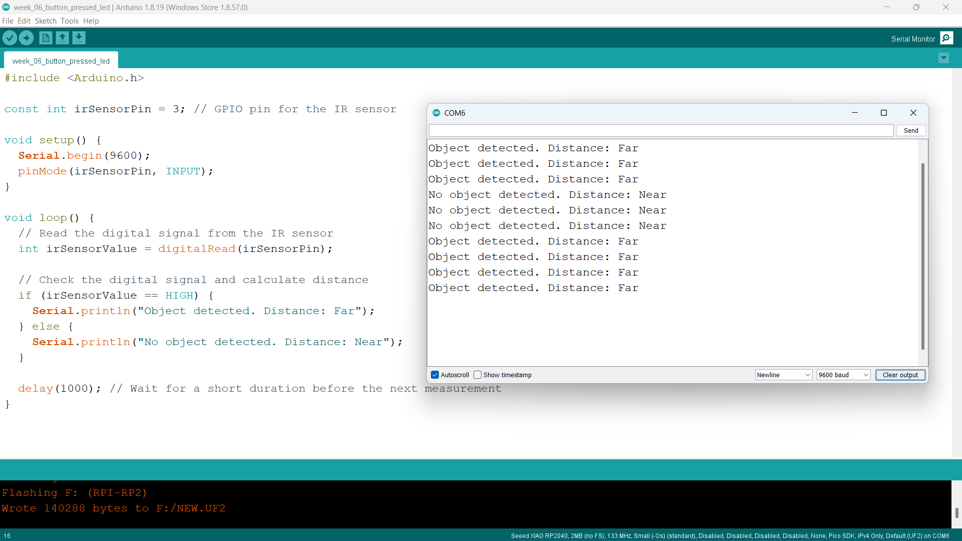
#include <Arduino.h>

    const int irSensorPin = 3; // GPIO pin for the IR sensor

    void setup() {
      Serial.begin(9600);
      pinMode(irSensorPin, INPUT);
    }

    void loop() {
      // Read the digital signal from the IR sensor
      int irSensorValue = digitalRead(irSensorPin);

      // Check the digital signal and calculate distance
      if (irSensorValue == HIGH) {
        Serial.println("Object detected. Distance: Far");
      } else {
        Serial.println("No object detected. Distance: Near");
      }

      delay(1000); // Wait for a short duration before the next measurement
    }
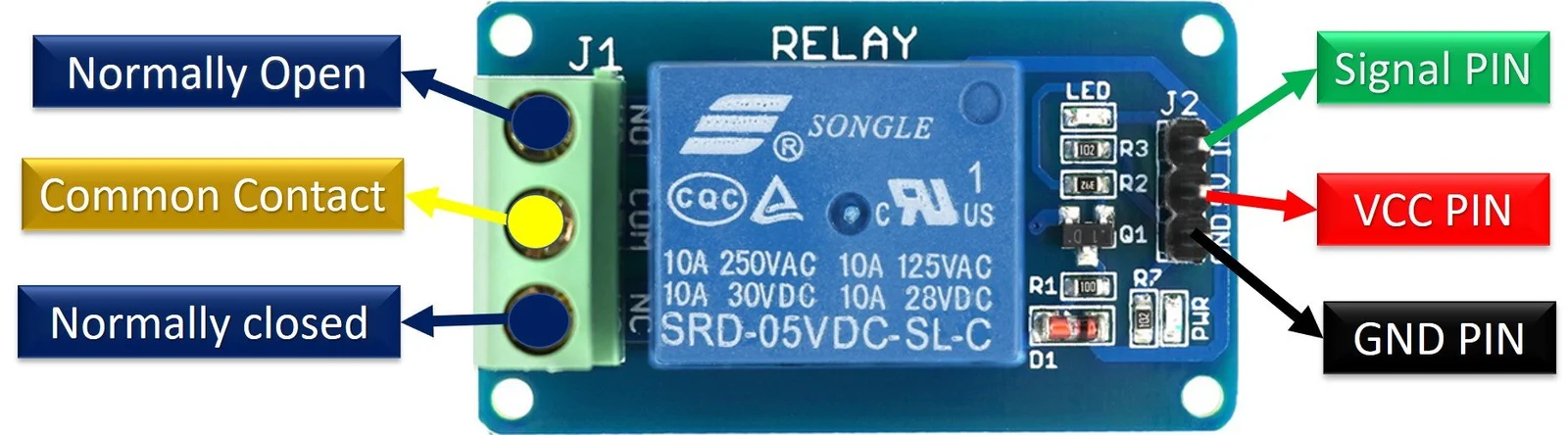
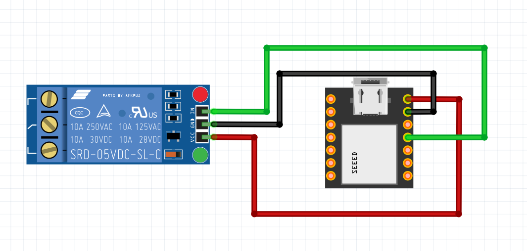
Relay Module
A relay is an electromechanical switch that is operated by an electrical current. It consists of a coil and one or more sets of contacts. When an electrical current flows through the coil, it creates a magnetic field that activates the switch mechanism, allowing the contacts to open or close.
https://youtu.be/n594CkrP6xE?si=AhGKtyoH0c5HMHT5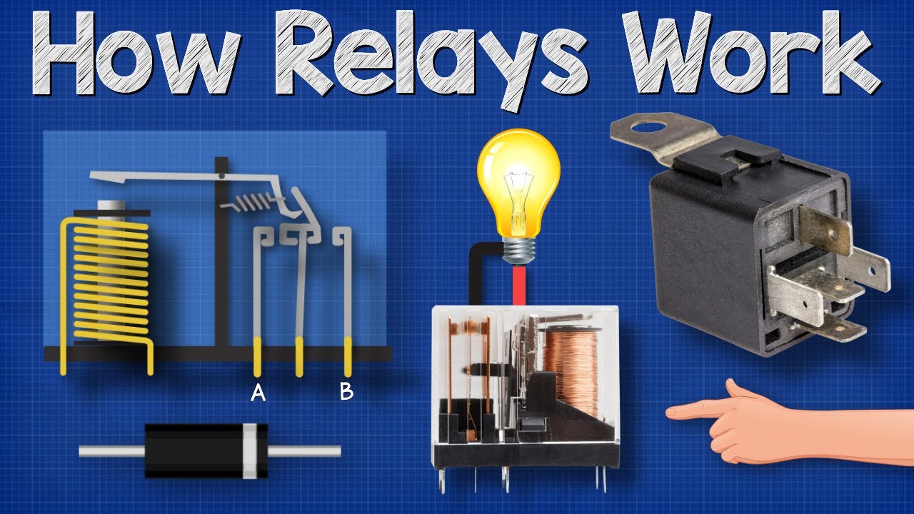
// Define the digital pin connected to the relay module
    const int relayPin = 3;

    void setup() {
      // Set the relay pin as an OUTPUT
      pinMode(relayPin, OUTPUT);
    }

    void loop() {
      // Turn on the relay for 2 seconds
      digitalWrite(relayPin, HIGH);
      delay(2000);

      // Turn off the relay for 2 seconds
      digitalWrite(relayPin, LOW);
      delay(2000);
}Wired Communication
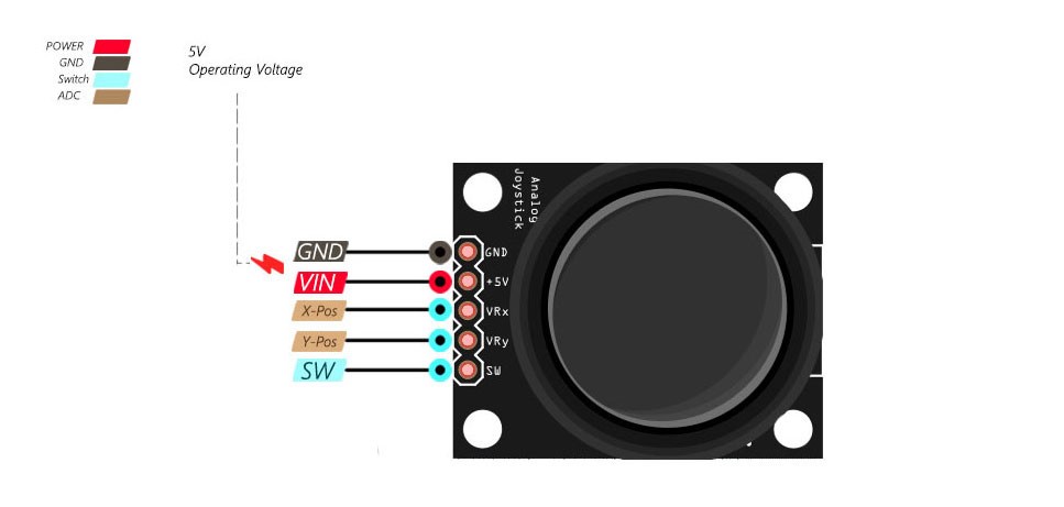
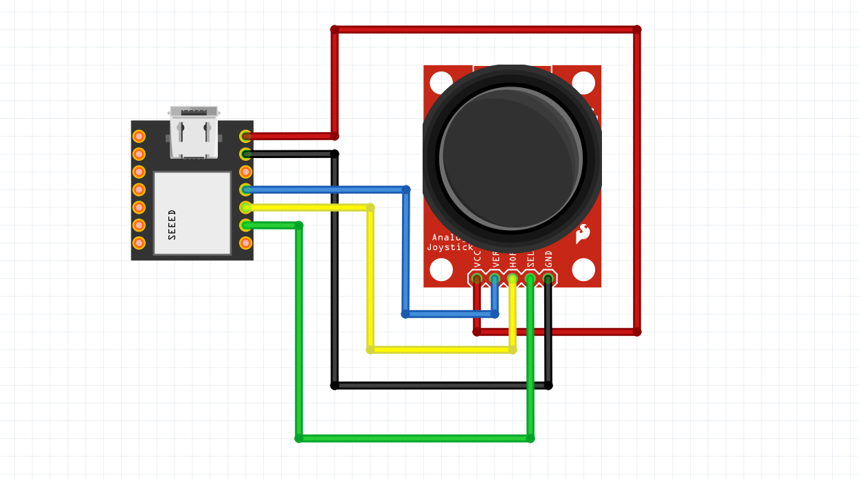
Joy Stick Module
A joystick module is a hardware component that provides a way to input control signals to electronic devices, typically used in applications such as gaming consoles, remote-controlled vehicles, and other interactive systems. It consists of a mechanism that allows users to move a lever or stick in various directions, and the module translates these movements into electrical signals that can be interpreted by a microcontroller or other electronic device.
https://www.youtube.com/watch?v=6N8Iq353GM8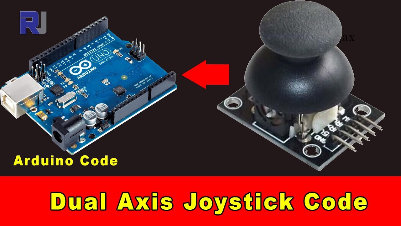
#include <Arduino.h>
#include <Servo.h>
// Define the digital pins for joystick button and X, Y directions
const int buttonPin = 2; // Change this to the desired button pin
const int xPin = 3; // Change this to the desired X direction pin
const int yPin = 4; // Change this to the desired Y direction pin
Servo servoMotor;
void setup() {
pinMode(buttonPin, INPUT_PULLUP); // Set the button pin as INPUT with internal pull-up resistor
pinMode(xPin, INPUT);
pinMode(yPin, INPUT);
servoMotor.attach(1);
Serial.begin(9600);
}
void loop() {
// Read the state of the button
int buttonState = digitalRead(buttonPin);
// Read the digital values from the joystick
int xValue = digitalRead(xPin);
int yValue = digitalRead(yPin);
if (xValue==0)
{
servoMotor.write(180);
}
if (yValue==0)
{
servoMotor.write(0);
}
if (buttonState==0)
{
servoMotor.write(45);
delay(500);
servoMotor.write(90);
}
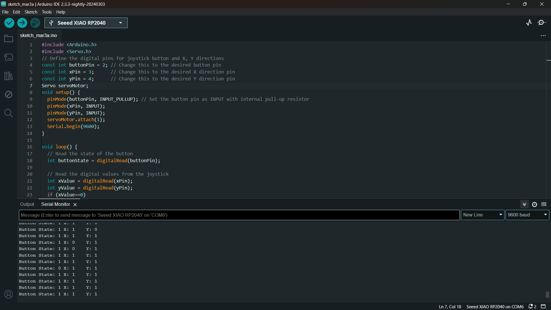
// Print the values to the Serial Monitor
Serial.print("Button State: ");
Serial.print(buttonState);
Serial.print("\tX: ");
Serial.print(xValue);
Serial.print("\tY: ");
Serial.println(yValue);
delay(500); // Adjust the delay based on your needs
}
Wireless Communication
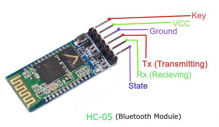
HC-05 Bluetooth Module
The HC-05 is a popular Bluetooth module commonly used for wireless communication in electronic projects. It is specifically designed for short-range wireless communication between electronic devices. The HC-05 is intended for short-range communication, typically up to 10 meters or 33 feet. This range may vary based on environmental factors.
https://youtu.be/BXXAcFOTnBo?si=zr2t9W6cKL8k72JR
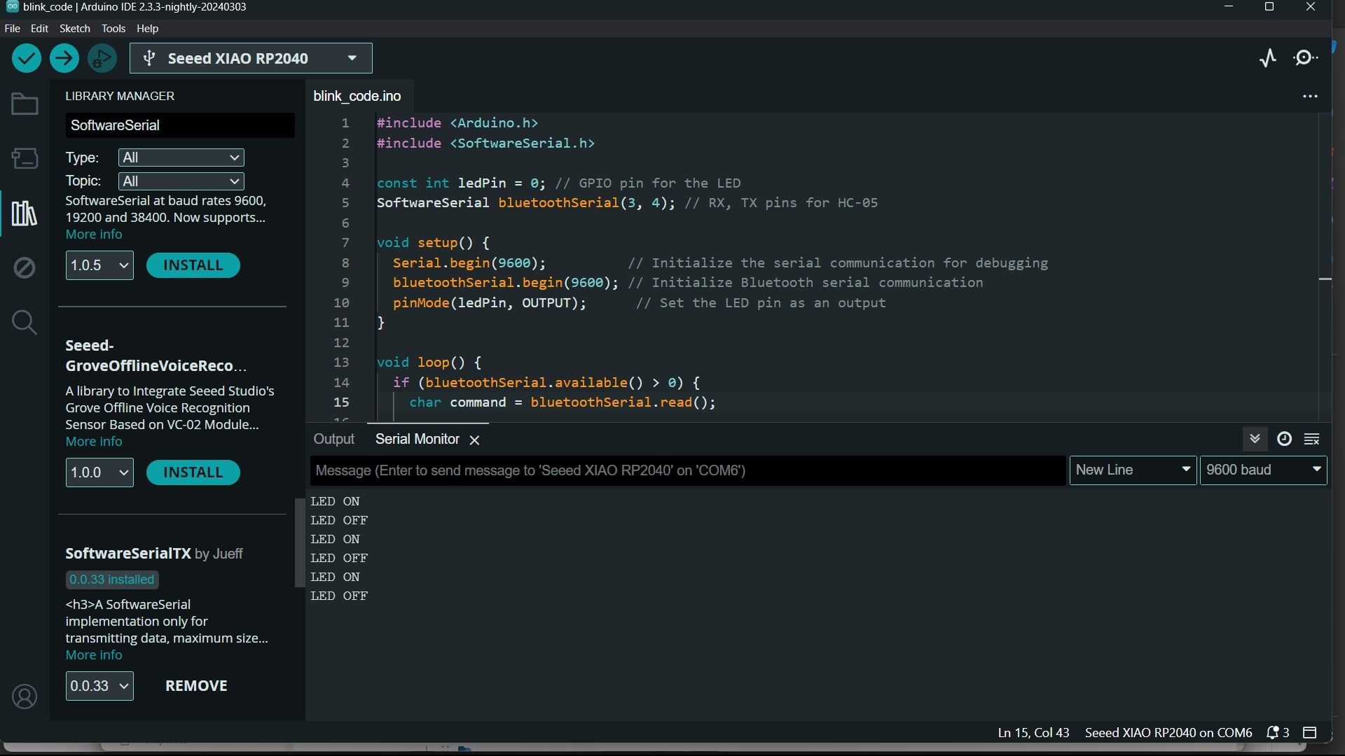
SoftwareSerial library
In Arduino IDE, the SoftwareSerial library allows you to create serial communication on any of the digital pins of your Arduino board. If you need additional serial ports or want to use pins other than the hardware serial pins (usually RX and TX), SoftwareSerial can be handy.
#include <Arduino.h>
#include <SoftwareSerial.h>
const int ledPin = 0; // GPIO pin for the LED
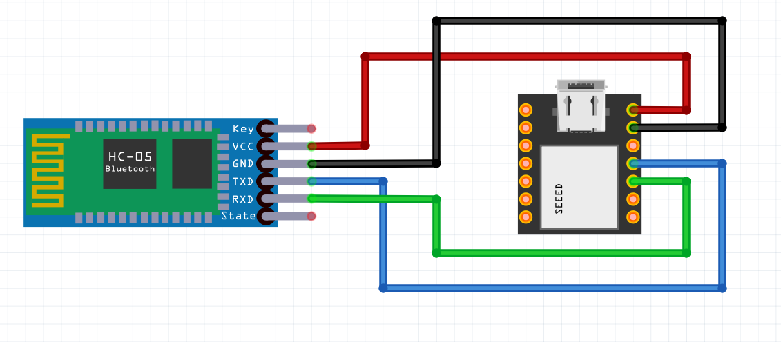
SoftwareSerial bluetoothSerial(3, 4); // RX, TX pins for HC-05
void setup() {
Serial.begin(9600); // Initialize the serial communication for debugging
bluetoothSerial.begin(9600); // Initialize Bluetooth serial communication
pinMode(ledPin, OUTPUT); // Set the LED pin as an output
}
void loop() {
if (bluetoothSerial.available() > 0) {
char command = bluetoothSerial.read();
// Toggle LED based on received command
if (command == '1') {
digitalWrite(ledPin, HIGH); // Turn on LED
Serial.println("LED ON");
} else if (command == '0') {
digitalWrite(ledPin, LOW); // Turn off LED
Serial.println("LED OFF");
}
}
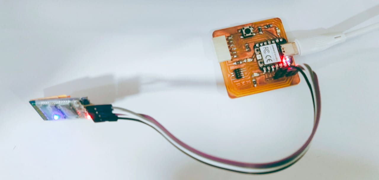
}- Open the arduino IDE
- Select the correct port and board.
Arduino BlueControl App
Arduino BlueControl app can be used to control your Arduino by sliders, buttons, and a joystick. Custom sliders and buttons can be used to interface with electronics components such as actuators and sensors connected to the Arduino.
- Turn on the bluetooth.
- Select the HC-05 module and type the password: 1234
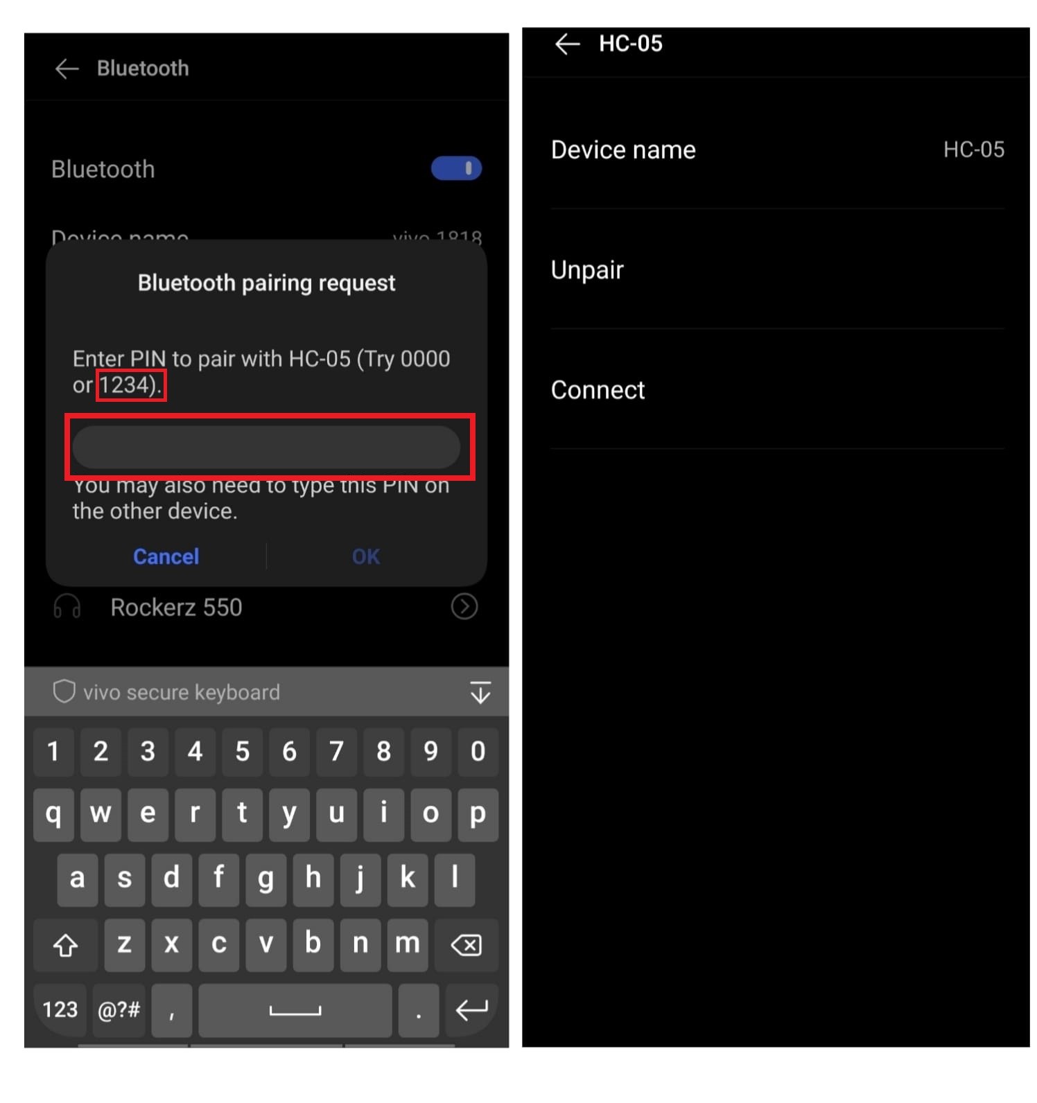
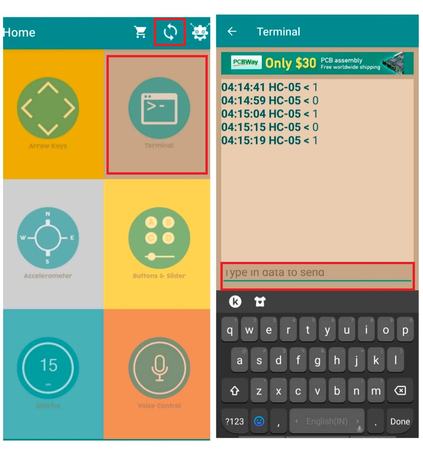
- Once the HC-05 got paired, open the Arduino BlueControl App.
- Select the connecting option to connect the HC-05 module to the App
- After connecting successfully, open “Terminal” and type “1” to turn on the LED, and “0” to turn off the LED.
Group Assignment Result

Reference
Resources and Downloads